HLT Work and Pictures

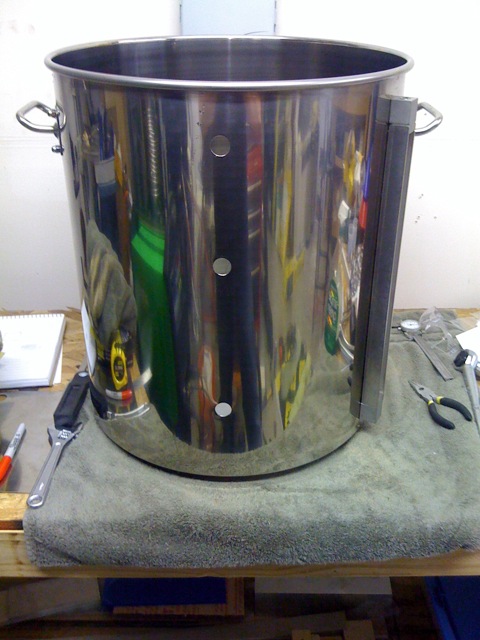
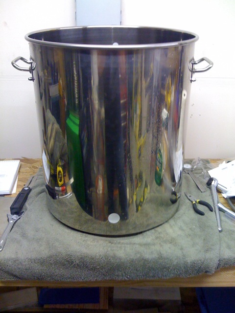
Took an hour or so tonight and finished cutting all the holes in the HLT. I had to drill a liquid return hole near the top of the kettle and cut the big 1.25″ heating element hole at the bottom. I put the liquid return at 2 inches from the bottom of the rolled to top of the kettle cause that looked like a good place to put it. The heater element hole went 3″ from the bottom of the kettle on the right side. I originally wanted to put the heating elements in the backs of the kettles for aesthetic reasons but decided at the last minute that I would have more room to work inside the kettle for adding accessories if I went in from the side.

For the large heating element hole I used a “chassis punch”, which is a new tool to me. It’s basically a heavy metal punch and die that the punch slips in to with a bolt through the whole thing. You drill a pilot hole, put the bolt through, put the punch on one side and the die on the other and tighten the bolt till you have a perfect hole. It worked well, but I am not sure it was any easier than the step drill I’ve been using for the 7/16″ holes. I also think the threads on the bolt stripped a little. My understanding is that Greenlee makes the best chassis punches, but they are kinda expensive. I picked up a knockoff from Radio Daze.

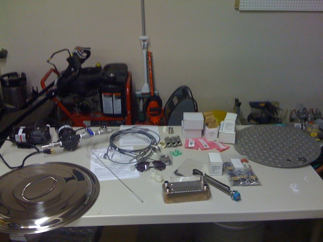
I also finally took some pictures. Here is the kettle with the 2 HERMS coil holes, the liquid return hole and the heater element hole and a picture of what I refer to as “The Loot Table”. This is all the stuff I’ve currently collected for the brewery. It’s going to overflow in the next week as the last of the orders all come in. I can’t wait!

So now all the modifications for the HLT are finally done and with any luck tomorrow I will be able to put it all together and start doing wet testing. Gotta make sure there are no leaks before I give it the juice!

Minor Progress

I made a little progress last night on the brewery but there is some other news to share!

First, progress: I picked up a tubing bender from Harbor Freight and it made quick work of bending the other 90 degree bend in my HERMS coil. I measured everything out and chopped off a few inches of each end of the coil so everything lined up and the coil is now ready to be mounted. I’ve decided to hold off on mounting it till I finish drilling holes in that kettle. It will be way easier to clean out the swarf, cutting oil and nasties without a giant coil mounted in there. I still need to cut a 1.25″ heater element hole, a hole for the temperature probe and a hole for liquid return near the top. It’s getting late tonight so this will probably happen tomorrow.

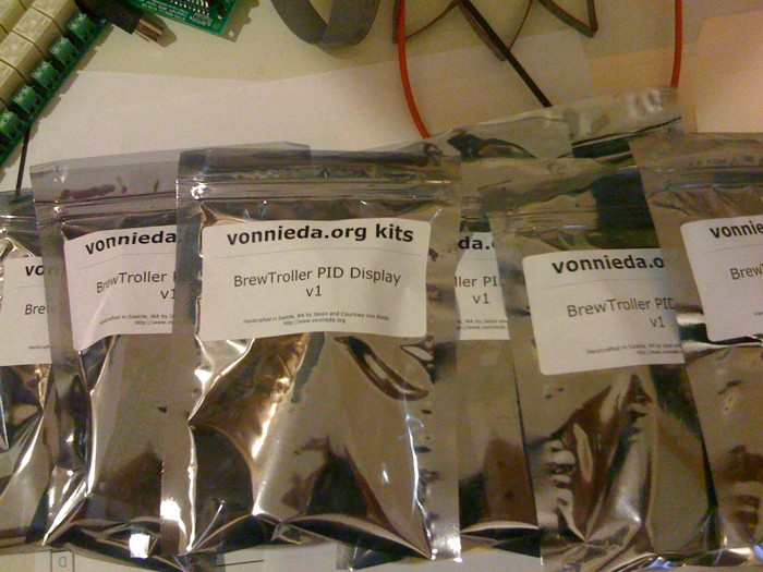
Next, kits: I ordered and received all the parts to make 10 BrewTroller PID Display kits so tonight Courtney and I made up the kits and printed some nice labels for them. Now they are in a box just ready and waiting for you to buy them!

Finally, parts: I ordered the last of the expensive parts for the brewery. I ordered a bunch of control panel components along with the enclosure that will actually be the control panel. It’s a 14x14x8″ steel, hinged and locking enclosure. I’ll post of a picture of the control panel design soon but basically it holds:

  • 1 key operated switch for main power with a large power light.
  • 2 3 position selectors along with lights for setting heaters to On/Off/Auto.
  • 2 3 position selectors along with lights for setting pumps to On/Off/Auto.
  • 3 BrewTroller PID Displays.
  • 1 BrewTroller LCD.
  • 1 Giant aluminum encoder knob for controlling the BrewTroller.
  • 11 (or more) small 3 position toggle switches + LEDs for setting valves to On/Off/Auto and for showing their status.
  • 1 large PANIC switch that cuts all power.

Inside the control panel will be the BrewTroller, 16 port relay board, 2 very large contactors for controlling power to the heaters, 2 SSRs for controlling heat, a compact computer power supply for lots of 12v current and lots of other little odds and ends.

Anyway, I also ordered the last of the valves I will need. 10 more of the little bastards. That was expensive but it’s gonna be awesome. Unfortunately I decided at the last minute I needed 11 valves (which I now have coming) but I only planned my control panel for 10 so I need to move a few things around and I will be short one damn LED.

I think that’s it for tonight! Looking forward to the weekend when I hope to make some serious, serious progress. Hopefully by then the rest of my kettles will be here, too!

HERMS, RIMS, Wattage and BTUs – A Treatise

Someone on a forum asked me what size heating elements I intended to use in my brewery. My answer was simple – but then I decided to try to do some math…

My batch size is going to be 10 gallons. I am planning on using a 4500 watt element for my HLT and a 5500 watt element for my BK. These numbers are based purely on random guesses. But… I’ve been wanting to know too. So let’s figure it out.

I just found this info on Wikipedia:


A BTU is the energy required to raise one pound of water by one degree Fahrenheit. A U.S. gallon of water weighs 8.3 pounds. So, to raise a 40-gallon tank of 55 °F (13 °C) water up to 105 °F (41 °C) would require (40 × 8.3 × (105 − 55) / 100,000) BTU, or approximately 0.17 CCF, at 100% efficiency. A 40,000 BTU/h heater would take 25 minutes to do this, at 100% efficiency.

In comparison, a typical electric water heater has a 4500 watt heating element, which if 100% efficient results in a heating time of about 1.1 hours.

Okay, so based on that info and the Wiki entry for BTU we find that the formula for calculating power required to heat water is: BTUs = (GALLONS * 8.3 * (FINISH_TEMP – START_TEMP))

And from http://www.mhi-inc.com/Converter/watt_calculator.htm we find out that 1000 watts is 3414 BTUs.

And based on random crap I found around the Internet we know that heating elements (and heat sources in general) are measured in BTUs per hour or Watt hours. i.e. how many BTUs they put out in an hour or how many watts they put out in an hour.

So now we just have to figure out the two formulas based on time.

So, using my case of a HERMS system let’s say I want to know how long it will take to raise 15 gallons of 55 degree water to my 170 strike temperature. That’s:

(15 * 8.3 * (170 – 55)) = 14317 BTUs

If I use a 4.5kW element I am creating (4.5 kW * 3414 BTUs per kW) = 15363 BTUs per hour

So my time to heat my water is 60 minutes / 15363 BTUs * 14317 BTUs = 55 minutes!

That was actually much less difficult than I expected

Based on that info, I think that I will put a 5500 in my HLT and the 4500 in my BK. The big difference here is the temperature difference. To go from tap water to sparge water it’s a 115 degree difference but to go from mashed wort at 156 to boiling it’s only 56 degrees – so it will make more sense to have the bigger heater in the MLT. It will save me about 10 minutes in heating my mash and sparge water.

Now, getting back to your original question – RIMS seems more difficult to calculate because the water is moving past the heating element. I’d need to think about it more but maybe that doesn’t matter. If water is always in contact with the element and water is constantly being moved through the tube maybe that’s the same as being in contact with all the water at once. You end up applying more BTUs to less water, so maybe it averages out. Let’s assume it does.

If you wanted to ramp 20 gallons 1 degree in one minute it’s:
(20 * 8.3 * 1) = 166 BTU hours * 60 minutes = 9960 BTU minutes / 3414 BTUs per kW = 2.9 kW. So, it seems like with a 100% efficient system you could use a 3kW element to get your steps. I think the real problems will be trying to get 20 gallons of wort past the element in 1 minute. It looks like my March 809 pumps are a max of 6 gallons per minute, so you’d need at least 3.3 minutes to get all the wort past the element.

I guess another option would be to oversize the element to decrease the amount of wort that needs to flow past it. If it will take 3.3 minutes to move your wort past the element, what if instead you use 3x the heat? If you use 3x the heat you would only heat 1/3 of your kettle but the wort would come out of the RIMS much hotter and would increase the total temperature of the wort.

So, there’s my attempt I am sure someone who knew anything about thermodynamics would just read this, laugh and walk away, but it’s probably better than guessing!

Brewery Build – Introduction, HERMS Coil, Drilling Boilermakers

It’s probably time I start posting about my brewery.

I’m building an all electric Heat Exchanger Recirculating Mash System (HERMS) brewery that will live in my garage. The brewery is intended to fix all the problems I had when I was brewing in Kansas and make brewing enjoyable instead of a horrible chore.

The basic gist of the system will be 3 20 gallons pots, the Hot Liquor Tun (HLT), the Mash Lauter Tun (MLT) and the Boil Kettle (BK). The HLT will contain a large coil of stainless steel tubing that wort will circulate through to change the temperature of the liquid in the MLT. This is the HERMS. The system will use two pumps to move all the liquids around and several (10, perhaps?) solenoid valves to make on the fly plumbing changes. The goal is that the system will require no manual plumbing changes and (ideally) could run almost 100% automatically.

I’ve been designing, drawing, dreaming and buying stuff for a month or so now. I made a giant shopping list and have been trying to buy the stuff needed to get a single kettle up and running and then go from there. This weekend I finally had most of that stuff together so I got to work. I wanted to build the HLT first since that would be the most complex. The first step was to fabricate the HERMS coil as the size of that would determine the positioning of many things. I picked up 50′ of 1/2″ OD stainless tubing McMaster and when it arrived it was in a 24″ diameter coil. Unfortunately I needed a 12″ coil. So, after doing some reading and asking questions I filled the whole thing with nice, dry sand (which was a pain in the ass) and very slowly and painfully coiled it around an old 12″ diameter pot I had laying around. This worked pretty well but it was HARD work! My coil turned out to be 12″ in diameter and about 8″ high when compressed.

Side note: When the project is done I will post a spreadsheet with prices and sources of all the parts. I don’t feel like putting them all in these posts as I go along.

That was Saturday. Sunday I measured everything, draw some dots and set out to drill some holes in my Boilermaker. This was fairly difficult but I think it was my own fear of drilling in the expensive pots more than anything. I drilled a 1/8″ pilot hole using lots of cutting oil and plenty of pressure with my hand drill and then widened each hole to 13/16 with a large Unibit. Lots of pressure, cutting oil and some good hearing and eye protection and it wasn’t really that bad. I drilled two holes on the left side of the pot. One at 5″ from the bottom and one at 13″ from the bottom. These are the entry and exit holes for the HERMS coil. I would have liked the coil to sit a little lower but I needed room for the heating element which will be at 3″ from the bottom. The holes needed to be slightly larger than 13/16″ so I cleaned them up just a little bit with a sanding wheel in my Dremel.

The next step was mounting the coil. I had intended to use a pair of weldless bulkheads, two 90 degree elbows and just run the coil right into the elbows. This turned out to not really work. Because of the angles involved the coil would rest against the side of the kettle. I tried using a coupler to move the whole assembly further into the pot but that made it go too far to one side and hit again. When I had really wanted to do from the beginning was have the coil terminate in two straight pieces from a 90 degree bend so it could go straight into compression fittings through the kettle wall. Unfortunately I had had some trouble doing 90 degree bends in the stainless tubing. Since this ended up being necessary I got to work on that.

To get my 90 degree bends in the tubing I first straightened about 16″ of tubing at the top of the coil. I did this by slipping a plumbing spring over the coil then straightening it about an inch at a time in my vice. This worked really nicely. Once it was straight I put it back in the vice around where I wanted my 90″ bend and started pulling on it. I would bend a few degrees and then move it in the vice a quarter inch or so and then repeat. This was hard work but it got the job done. The only problem is that the resulting bend has a very slight kink to it. I don’t think it will cause too much restriction but only time will tell. I tried to reshape the kink in the vise a little and had moderate success.

That’s where I finished on Sunday. I have another 90 degree bend to make and then I should be able to mount the coil. I am thinking I might pick up a tube bender from Harbor Freight and try that. They sell one for $30 that looks like it might be capable.

So, tonight I’ll try to make the other bend, mount the coil and test it all out for water tightness. After that it’s on to installing the first heating element. I bought a 1.25″ chassis punch that should make that a lot easier but it’s not here yet. Should be here soon. I’ll also be receiving a bunch of control panel parts tomorrow that I can start laying out and seeing what works.

Also, I should mention I built and am selling a custom display for the BrewTroller brewery controller I am using. Check it out!

And finally this is a quick rundown of the specs and major components of the brewery I am building:

  • All electric HERMs brewing system. 240v, 50A input.
  • 3 20 gallon Boilermaker kettles.
  • 240v 4500 watt HLT and 5500 watt BK.
  • Control provided by a BrewTroller v3.3 w/ 16 relay output board and BrewTroller software 1.2.
  • 3 Custom PID temperature displays.
  • 2 March 809-HS pumps for fluid movement.
  • 7-10 stainless steel 12v solenoid valves for fluid routing.
  • Plate style stainless steel wort chiller with 20 plates.
  • Silicone tubing plumbing to start, stainless hard plumbing eventually.
  • Custom stainless brewing stand. I’ll be welding this once my TIG skills are a little better.
  • Custom control panel with On/Auto/Off controls for pumps, heaters and all valves. Also includes 3 of my BrewTroller PID Displays, the BrewTroller LCD and rotary encoder for input.
  • All stainless pipe fittings.
  • Inline oxygen injection during pump to fermenters.
  • Constant recirculation of MLT and HLT to avoid temperature stratification.

I think that’s it for now!

Sigh…

Man, I never post any more. It makes me kinda sad. I like posting! But I am so damn busy doing shit that I never feel like I have to time to write up a proper post about all the stuff I did and it just piles up.

The last few weeks have been kinda crazy. For a few months now we’ve had a lot of travel planned for May and then at the last minute I added another one. My brother has been threatening to put a supercharger on his 2005 Lotus Elise for a while now and he finally decided to do it. I had expressed some interest in helping with the install, so when he ordered the kit I booked a flight to Kansas City. It was a short trip but lots of fun. I got in Friday afternoon and spent the evening hanging out with friends at Barley’s, then we got up for an early start on the supercharger Saturday morning. We were expecting around 12 hours of work, and it ended up taking more like 20 but man it was worth it. We worked from 8am till about 7pm on Saturday and ended with the supercharger stuck about halfway in. We had skipped a step involving moving the alternator early on and we ended up having to go back and do it the next morning.

So, bright and early Sunday morning we got up, moved the alternator and it was pretty smooth sailing the rest of the way. Minus one pipe that we had to modify more than recommended the install went pretty smooth the whole way. Not to say it was easy: It wasn’t. I had bruises and cuts and sore muscles for a week afterward.

I wrapped up my KC trip at Gengis Kahn with a few friends, then got up at 3am and flew back to Seattle. Short, but long trip 🙂

Next up was New Jersey. My step-dad Fred has been dating a lovely lady named Dori for quite a while now and last year they decided to marry. After getting the invite we planned a trip out for the wedding and for Courtney to get a chance to see where I grew up and meet some family. It was also a short but action packed trip. The wedding was very nice, and I got to spend lots of time with family I seldom see. Courtney got to meet quite a bit of my family. We also managed trips to Dippy’s, Sals and Steak Out for traditional NJ grub and we visited my old house in Sewell, and in Mantua.

We also took a trip out to the cemetery where my Dad is buried so that I could see his grave. The day of the funeral his marker had already been placed and it had snowed the night before so I couldn’t see it and didn’t know where it was. That part of the trip was pretty painful, but much needed.

Finally, we took a drive past von Nieda park in Camden since I had not been there in years. It seemed like a really great place to get killed so I took a picture of the sign and we got the hell out of there. Off to the airport and back to Seattle!

Next up was the Bay Area Maker Faire in San Mateo, which we just got back from Sunday. I don’t have a whole lot to say about it this year. There were some cool exhibits but most of it I had seen last year. Maker Faire seems to be very geared towards kids and families, which I think is awesome but it’s not awesome for me. I am really glad this exists for kids to get excited about science and hacking and DIY but I found myself kinda bored this time around. The exhibits that stuck out in my mind were the Mondo Spider which is a huge, hulking, ridable metal spider and the big POV sphere in the middle of the Tesla coil hall. On the downside, I am pretty worn out by “art” exhibits that aren’t much more than a propane tank and a source of ignition. I guess that stuff is is awesome when you are tripping your ass off at Burning Man and it’s dark out but I just don’t see a lot of value in blowing off a bunch of fossil fuels to make pretty flames.

Also: Get off of my damn lawn!

Anyway, we hit Maker Faire Saturday morning and stayed till about 4, then again Sunday morning and stayed till about 2 when I had a massive allergy attack. After getting back to the car so I could take some medicine we decided we were done and headed out to see a little bit of California before we had to fly again. We ended up kinda randomly on the coast and cruising down Highway 1 which was really a lot of fun. Absolutely beautiful everywhere you looked. It really deserved to be driven in a convertible. We ended up at the Pigeon Point lighthouse before turning around and that was really pretty. Courtney took lots of pics with our new Olympus EP-1 which takes really great pictures. After that: more driving, more flying and back in Seattle again! Our dogs are starting to think we only live here about 50% of the time now.

Our last trip is this weekend to Denver to see John and Aoi right before they are with baby, and to hang out with the rest of the crew. Really looking forward to this trip but I am sure not looking forward to flying again. This is the last trip for a while. A long while, I hope.

In random other news I’ve:

  • Bought an Everlast PM-205 TIG/Stick Welder / Plasma Cutter combo and am learning how to TIG weld.
  • Am building a badass, mostly automated 10 gallon, all electric brewery for the garage.
  • Am still hoping to finish the first OpenPNP prototype this year.
  • Started fixing up my bicycle. I’m hoping to start riding a little and get back in shape.
  • Sold one of my TC18 clocks on eBay and it fetched a princely sum!

I think that’s all for now. Bye!

140 Characters Found Too Confining

Today was ultra-awesome productive! I got up, fixed the lawn mower, mowed the lawn, cleaned up a lot of the mess in the backyard that Flux has made, went for a long motorcycle ride (Woodinville, Duvall, Monroe), almost pooped when a train blew it’s horn like 5 God damn feet from me, charged Courtney’s car battery and got that running, tested my generator to prep for sale, cleaned up the garage, scoped out the iron pipe offerings at Lowes (for future “shop air” project), put the hinges and clasp on the box for the eBay clock (coming soon!), got nicely buzzed and stuffed at Rock Bottom and am looking forward to a very nice night of blissful sleep.

Also, Courtney took an Introduction to Electronics class at Metrix which sounds like it was very informative!

And I spent a significant amount of time trying to figure out if I can really stick a 3 ton milling machine in my garage. Survey says? Yes we can!

Die Spammer, Die

Been getting a lot of spam recently on this site. Lots of stuff where someone will post a comment that almost sounds like a real comment but it’s just bullshit and their URL points to a poker site, or a porn site, or a SEO site, or in the case of one of my posts titled “Tranny”, a site you don’t want to know about.

For that reason, I’ve removed the ability to include your “website” URL when you post a comment. I’ve also caused any post that contains one or more URLs to be moderated by myself. Hopefully that will stem the tide. You can of course leave a URL in the comment if you want to, it just means I’ll look at it in person before approving it.

A New Beginning

In a rapidly assembled, last minute (although intended for quite some time) wedding, Courtney and I got married on Saturday, March 13th! We were married by retired judge Hayek at her office in Kirkland and it was very low key. Adam, JoLynn, Scott and his new woman Anissa were in town for Courtney’s birthday party (also the 13th) so we asked them to come along. It was a 5 minute ceremony and then we headed to the Irish pub around the corner 🙂

So, that ends one era of my life and begins another. I’m very much looking forward to what it brings!

Anodizing @ Home

The other night I finally finished buying all the supplies I needed to try to anodize some aluminum parts. Anodizing is a process that causes aluminum hydroxide to grow into and out of the surface of aluminum metal. Aluminum hydroxide is very hard, which provides scratch protection and is also porous which allows dyes to color it. Dying the metal is reason for a lot of commercial anodizing and is the main reason I am doing it.

The basic process of anodizing is to form an electrical circuit between the part to be anodized (the anode), dilute sulphuric acid and (usually) another piece of aluminum which is the cathode. Voltage is passed through the circuit which causes the anodizing to take place. The part is then dyed and finally the pores are sealed to keep the dye in.

This post describes how I did it.

First, some safety. Most of the stuff that I am doing to anodize parts can blind or kill you. Always wear gloves. Always wear goggles. Never mix chemicals unless you know what will happen. A few of these chemicals mixed will produce horrible gases that will kill you and your family and probably your dogs too.

Next, the supplies. I bought the following:

  • Battery acid, 5 gallons, from NAPA Auto Parts
  • Lots of distilled water
  • Several plastic buckets from Home Depot
  • 1 pound tube of 1/16″ aluminum tig welding rod from Central Welding Supply
  • 40 amp battery charger from Harbor Freight
  • Black RIT Dye from the supermarket
  • 2 single burner hot plates from Target
  • 2 6 quart pots for the hot plates

The first step is to get the parts nice and clean. I first washed them in warm water and hand soap and then in a dilute mixture of Simple Green and distilled water.

Next I used the welding rod as simple aluminum wire and attached pieces about 6 inches long to each part I wanted to anodize. You have to make sure the wire is attached very well, and also keep in mind that wherever the wire is attached the metal will not anodize. Lots of people use threaded holes and jam the wire in. I just made some little clips by bending the wire.

Next I took 1.5 gallons of my battery acid and mixed it with 1.5 gallons of distilled water. I kept in mind the AAA rule. Always Add Acid. If you add water to acid the water can boil and “explode”. I put 1.5 gallons of distilled water in a plastic bucket and slowly poured the 1.5 gallons of acid in. Very slowly. Probably took me about 5 minutes.

Next I used some aluminum scrap I had laying around to make a cathode and used some as a rack for the anodes to hang from. It’s pretty clear from the below picture:

I drilled a bunch of holes into the anode rack to use as hook hangers and bent the ends of the anode wires into hooks. Hang the parts.

Next step is to apply the juice! Hook up the negative from the battery charger to the cathode and the positive to the anode rack. I’ve read that it’s best to start at low current and ramp it up. My charger has settings for 2 amps, 10 amps and 40 amps so I set it to 12 volts, 2 amps and let it run for 5 minutes. Almost immediately there were bubbles forming around the cathode. The bubbles are hydrogen gas which comes to the surface. Make sure you have some ventilation so you don’t blow up your house. Remember the Hindenburg.

5 minutes later I turned it up to 10 amps and then 5 minutes later I turned it up to 40 amps.

(I should probably note that I am running this batch as I type this post. Most of the experiences for this post come from a batch I did the other night with slightly different gear. )

At this point I let the anodizing bath run for about 80 more minutes. I have read that anywhere from 45 minutes to 90 minutes is good.

There’s a few ways to tell the anodizing has finished. The current draw should drop quite a bit. An anodized surface does not conduct electricity well, so as the surface becomes more anodized the part conducts less electricity. You may also notice a slight lemon yellow tint to the part. I just let it run for 90 minutes and called it good.

Once the parts are finished, turn off your power supply and rinse the parts very well in cold, clean water. The water must be cold or the parts will start to seal.

Next up is the dye. I used RIT Dye which seemed to work pretty well. There’s lots of places to get proper anodizing dye but RIT seems to work for me. I dumped a bottle the black, liquid RIT into 1 gallon of distilled water and put it on the hot plate. The dye works best heated and most people recommend about 140 degrees so that’s what I used. Once the dye was up to temperature I put the parts in and let them soak for about 15 minutes. I have read that you might get the color you need in as few as 15 seconds depending how dark you want it. I wanted dark, dark black so I left them in for 15 minutes.

At this point you can pull the parts out and you may find that some didn’t take any dye or the dye drips right off. This happened on my first batch with one part. What this means is that you didn’t have a good electrical connection to the part. You can remove the dye and anodizing by etching it in a bath of water and lye. I used a few tablespoons of lye in about a half gallon of distilled water.

Once the parts are dyed the only thing left to do is seal them. This is done with boiling water. I read that steaming the parts before putting them in boiling water can help you lose less dye, so I put a pot of water on my other hot plate, put a rack over the pot and placed the parts on the rack. Then I boiled the water letting the steam wash over the parts for about 10 minutes. Then into the bath they go. 30 minutes in boiling water and the parts should be sealed and ready for use! Hooray!

I’m still a total newbie at this, and I’m actually going to a professional anodizing shop next week to see how they do it. That said, I did get really nice results and it seemed pretty easy. Takes some time and a few dollars but the result is amazing!

My pictures of the finished results are here and Courtney’s pictures of the process are here.